Just installed Civil 3D 2017? Maybe just downloaded Civil 3D 2017 v1? Well never fear….2018 is here!! That was somewhat sarcastic, but I do some see much needed improvements to AutoCAD 2018 and its vertical products such as Civil 3D. You saw throughout the year with most Autodesk products that you get more periodic updates. Civil 3D 2017 v1 was a great update and I see this trend continuing.
This article looks at some of the top new features within AutoCAD Civil 3D 2018 and may help you make your decision to download and install today.
Version Interoperability
This may be a sticking point with many people moving forward with Civil 3D, and I completely understand why. However, Autodesk hasn’t changed the file version since AutoCAD 2013, but AutoCAD 2018 uses a new file format. It means unless you save the file to an older version, you can’t open AutoCAD 2018 files with AutoCAD 2013-2017.
How does that effect Civil 3D? Objects saved in AutoCAD Civil 3D 2018 are available only as proxies when the drawing is opened in a prior version of the software. Within AutoCAD Civil 3D 2018, set the PROXYGRAPHICS drawing setting to 1 to save the graphics with the drawing, otherwise you get all the bounding boxes when the drawing is opened in a prior version of the software.
Civil 3D 2017 v1 Features
Most, if not all, of the Productivity Pack enhancements have been rolled into the software, along with other subscription perks throughout the 2017 release.
Here are a few additional enhancements to note:
• Analyze Gravity Network
o Resize pipes and reset inverts and compute the energy and hydraulic grade lines according to HEC-22 2009 standards.
• Swap Pressure Parts
o Swap pressure network pipes, fittings, and appurtenances with parts of another size or type.
• Traverse Editor/Adjustments
o Input, edit and apply an adjustment method to traverse data.
Production Efficiency
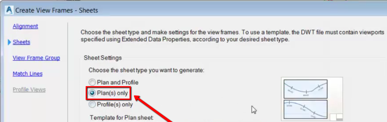
Create Plan/Plan sheets as well as Profile/Profile Sheets.
You now have more options when utilizing the plan production tools. You have a Plan/Plan option as well as a Profile/Profile option. I know the plan/plan will be a big help to individuals that I consult with often. This may seem like a simple thing, but the extra flexibility will really help in those projects where plan views and sections are the main aspect.
There are new templates that ship with 2018, but it is a simple fix within your current plan production template as well.
Move sections views from one section view group to another
You can now move section views between section view groups and update the sheet layout. When updating the section view layout, resized or inserted section views are respected.
Add Property Set Data to Labels
This came out with the 2017 v1 release, and I feel this is a huge, often overlooked, capability of Civil 3D. So, I chose to highlight this a bit more.
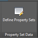
First thing to do launch the PropertySetDefine command, or from MANAGE tab on the ribbon, to the far right, select DEFINE PROPERTY SETS.
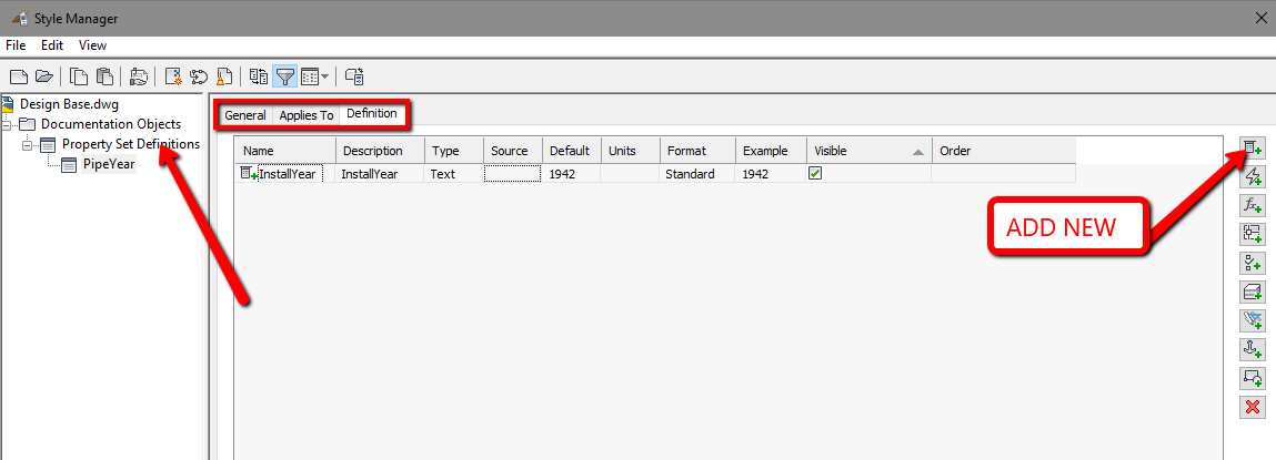
Right click on Property Set Definition and select NEW. For this example, I will use PipeYear, as I want to label the year installed on my pipes.
On the “Applies To” tab, select the type of object you want to create a custom property for. I chose PIPE for this example.
On the Definition tab, add your new properties. Click the top button on the right side (ADD MANUAL PROPERTY) to create the new property, and then fill in the data. I chose to call mine InstallYear.
Select OK.
One more step in order to see this new property. On the Extended Data tab of your properties, you’ll need to select the object (or objects) you want these properties to be assigned to and click the button at the bottom left of the properties, “Add Property Sets”.
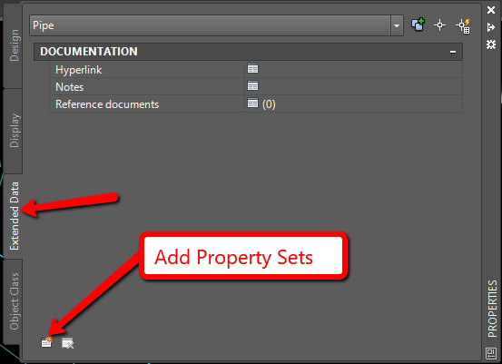
This will bring up another dialog box. Choose the property(s) you wish to add to the objects, and select OK. You will now see them in your properties dialog box!
That is where it ended in 2016. But now, with 2018 (2017 v1), we can now add that to a label style! Once you go into your label style composer, and select one of the components to edit, you now have a third tab called “Property Sets”! You can select and add to your styles as needed.
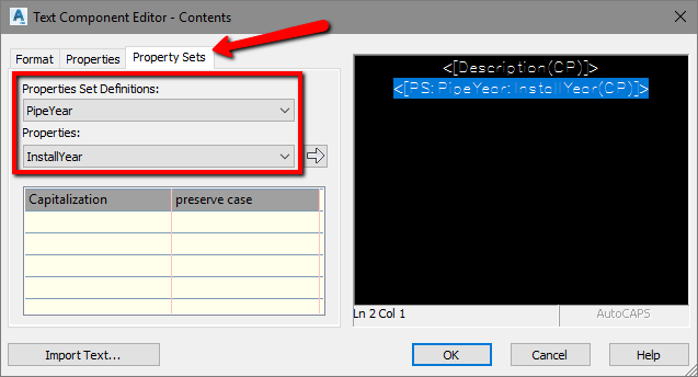
The possibilities are endless with this function. The example above shows you how to add custom properties in order to label. But you can also add custom properties that are derived from the objects themselves! For example, if you want to know the volume of a surface, you have to view it in the Surface Properties, or use the Volumes Dashboard. But you can now view the automatic data for one object at a time. Very cool in my opinion!!
Design Efficiency
Create Feature Lines that are dynamic to surfaces!
This is a fantastic update, and one that is well overdue. Feature line elevations can now be obtained from a surface and can also be relative to a surface, so if the surface is updated, the feature line is updated.
The update behavior of relative feature lines is different depending on whether the feature line was set to be relative to a surface when it was created, or whether it was created at fixed or non-dynamic elevations and then set to be relative.
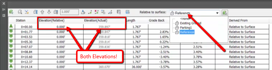
Create offset alignment profiles that are relative to the main alignment baseline
You can create dynamic offset profiles using the same command you use to create offset alignments. The profile geometry is offset using a default cross slope which you can modify by editing the profile properties. You can create multiple offsets in a single operation, including a different number on each side of the parent alignment. The offset distance can be different on each side of the parent alignment.
Useful why? Maybe you have to show a borrow ditch, TBC profiles or pretty much anything that is relative to your main profile. There are current work arounds, but this should help out a lot of people.
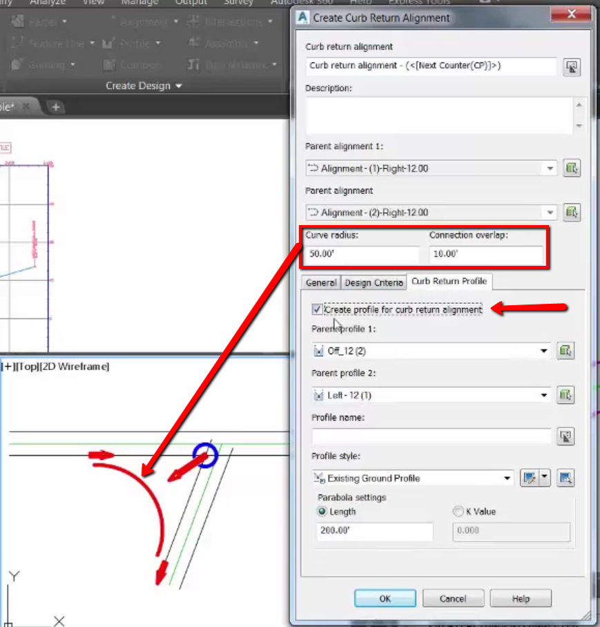
Create Connected Alignments & Profiles
You can use the connected alignments feature to create a new dynamically linked alignment and profile that transitions between two selected alignments and their profiles. You can use this feature to create a curb return, an exit ramp, a merging/diverging road, or you can connect an existing road with a proposed road. The connected alignment is created between two selected alignments at a specified radius. The geometry of the connected profile is automatically generated from the parent profiles that you select. The start and end elevations and slope are taken from the parent profiles, and the middle section of the connected profile is calculated depending on whether extensions of the parent profiles intersect.
A lot going on there right? This streamlined method works great for manually creating those intersections and will save a lot of time on editing.
Resolution of Corridor “Bowties” in daylight conditions
Where corridor tangents intersect at a corner, and where the corridor is created at a fixed width, the inner and outer corners of corridors are cleaned up automatically. If you have a corridor that you are bringing forward from a prior version of AutoCAD Civil 3D, and the corners need to be cleaned up, all you need to do is a simple edit to the corridor and then rebuild it. In other situations, when the corridor is created at a non-fixed width (such as when daylighting to a surface), you can use the CLEARUPCORRIDORBOWTIE command.
AutoCAD 2018
As usual, Civil 3D will include all the base product enhancements of AutoCAD 2018. See the article for What’s New in AutoCAD 2018 for detailed info, but I did want to mention the following enhancements that I think may be a great addition to your workflow.
XREF Improvements – If you utilize a lot of XREF’s, then you will really enjoy this feature
• Now XREFS default to relative, reducing broken paths.
• Easily find and apply the correct path to missing references.
• When you right click on a missing file in XREF palette, you can see there are new items in the contextual menu. Select New Path and Find and Replace.
BING Map Service
• Support for Bing Maps v8.0
Enhanced PDF Import Options
• Intelligently bring in text (SHX and TrueType text) and geometry from PDFs and use them like any other AutoCAD object.
• Use the SHX text recognition tool to quickly convert imported geometry from SHX text to text objects. The SHX text recognition tool analyzes clusters of geometry and automatically replaces them with Mtext objects.
Conclusion
There may not seem like a ton of new features, but the new features and enhanced features will help in your everyday workflows.
I would love to hear from you regarding the new features and features you would like to see added or enhanced, so feel free to reach out to me anytime.
Related Blog Posts